Checklist: Pre-Placement Inspection for Concrete Pumps

A pre-placement inspection of a concrete pump checks hydraulic systems, hoses, safety interlocks, and structural components. Engineers use this checklist to verify pump readiness, reduce downtime, and prevent equipment failures during placement operations.
- Inspect hydraulic hoses for abrasion, bulges, and proper clamp tightness before connecting to the pump.
- Test safety interlocks, such as boom stoppers and anti-reverse valves, to confirm they prevent accidental movement.
- Verify pump pressure settings match the concrete mix design and placement height.
- Check structural components like booms, outriggers, and base units for cracks, weld damage, or wear.
- Keep a documented record of each inspection to support maintenance planning and liability protection.
Why pre-placement inspection matters
A concrete pump moves high-pressure material through long hose lengths and elevated booms. A single failed hose or stuck valve can stop a pour, damage the pump, or create a serious safety hazard. The pre-placement inspection is the final verification step before the pump is connected to the mixer and the first batch of concrete is placed.
This is not a routine maintenance check. It is a readiness verification. The operator or engineer confirms that the pump is in the condition required for the specific job. The checklist below covers the systems that most often cause failures or safety issues during active placement.
Each item is grouped by theme. The explanations describe what to look for and what a defect indicates. Red flags are listed to help you recognize problems quickly.
1. Structural and chassis inspection
The base unit, boom, and outriggers carry the mechanical load of the entire pump. Before the pump is positioned, walk around the unit and inspect the structural components.
Check the base unit frame for cracks, deformation, or weld damage. The base supports the hydraulic power unit and the pump. A crack in the frame can propagate under load. Look for rust that has eaten through the steel. If the base sits on a pad or mat, confirm the mat is thick enough and the pad is level.
Inspect the boom sections. Each joint has hydraulic cylinders and pins. Look for bent pins, worn bushings, or leaking cylinder seals. The boom must hold its position without drift. If the boom sags or drifts when a load is applied, the hydraulic system is not holding pressure.
Check the outriggers and legs. The pads should be flat and free of cracks. The hydraulic rams should extend and retract smoothly. If an outrigger pad is dented, the load distribution changes. The pump can tip or the pad can sink into soft ground.
Red flags:
- Visible cracks in the boom or base frame
- Bent or missing pins at boom joints
- Outrigger pads with deep dents or cracks
- Base unit sitting unevenly on the ground
2. Hydraulic hose and connection inspection
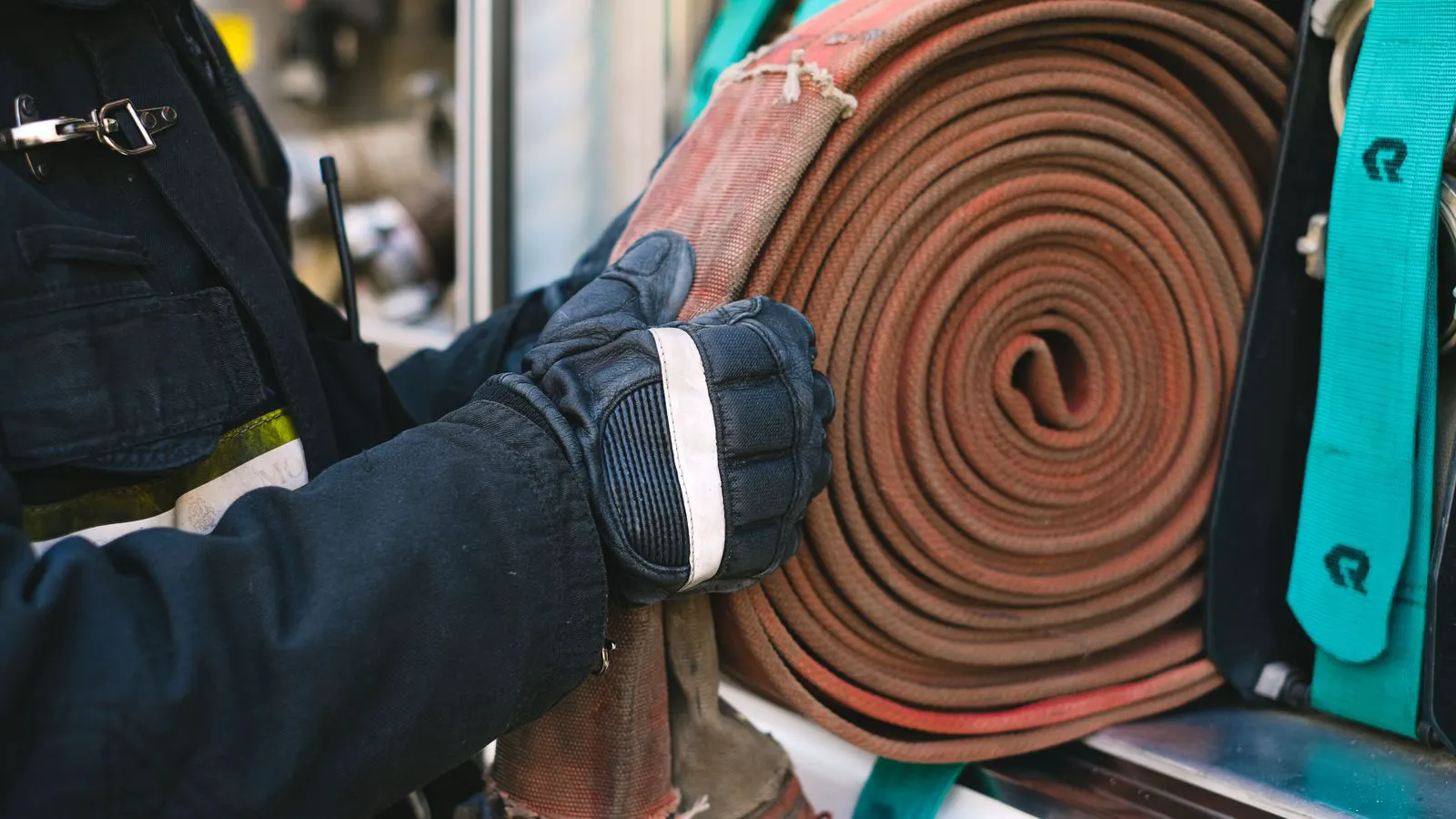
Hoses are the most common point of failure. High-pressure concrete pump hoses carry loads that can exceed 350 bar in some systems. A small abrasion can become a burst point after a few cycles.
Trace each hose from the pump to the boom and from the boom to the discharge point. Look for abrasion where the hose rubs against the frame, the boom, or the ground. Chafed rubber is a clear sign of wear. If the hose has been kinked, it may have internal damage even if the outer cover looks fine.
Check the hose clamps. Each hose fitting should have a clamp or a welded connection. Loose clamps allow the hose to separate from the fitting under pressure. A separated hose can spray concrete at high velocity, which causes burns and eye injuries.
Inspect the hose for bulges. A bulge indicates internal damage to the wire reinforcement. A bulged hose should be replaced immediately. Do not attempt to repair it in the field.
Check the couplings. The male and female ends of each coupling should be clean. Concrete residue builds up in the couplings and prevents a proper seal. A dirty coupling causes leaks at the connection point.
Red flags:
- Chafed or cracked hose outer cover
- Bulges or kinks in the hose
- Loose or missing hose clamps
- Concrete residue inside couplings
3. Pump and power unit inspection
The hydraulic power unit drives the pump and the boom. The pump itself is the component that moves the concrete. Both need a pre-placement check.
Start the power unit and listen. The engine or motor should run at a steady idle. Abnormal noise indicates a problem. A whining noise from the hydraulic pump can mean low oil level or air in the system. A knocking sound from the engine indicates a mechanical fault.
Check the hydraulic fluid level. The sight glass or dipstick should show the fluid at the correct level. Low fluid causes air ingestion, which leads to cavitation and pump damage. The fluid should be clean. Dark, gritty fluid indicates wear or contamination.
Check the pump. The suction line connects to the mixer or the hopper. The discharge line connects to the hose. The pump seals must be intact. A leaking seal allows concrete to enter the hydraulic system or allows hydraulic oil to enter the concrete line.
The pump has a relief valve. The relief valve protects the pump from overpressure. If the relief valve is set incorrectly or fails, the pump can be damaged when the system is overpressured.
Red flags:
- Low hydraulic fluid level
- Dark or gritty hydraulic oil
- Unusual noise from the engine or hydraulic pump
- Visible leaks at pump seals
- Relief valve not accessible or not labeled
4. Safety interlock and control inspection
Concrete pumps have safety features that prevent accidental movement and protect operators. The interlock system must be tested before each pour.
The boom stopper or hold-down system prevents the boom from moving when the operator is not in control. Test the stopper. It should lock the boom in position. If the stopper fails, the boom can move unexpectedly and strike personnel or structures.
The anti-reverse valve prevents concrete from flowing back through the hose when the pump stops. Test the valve by running the pump for a short cycle, then stopping. If concrete flows back, the valve is not working. A failing anti-reverse valve can cause hose collapse and make the pump harder to start.
Check the emergency stop. The e-stop button should shut down the pump and the boom immediately. Test it from the operator station. The e-stop should be accessible and clearly marked. If the e-stop is not working, the operator cannot stop the pump in an emergency.
Inspect the control panel. The pressure gauge and flow meter should show accurate readings. If the gauge is stuck or the flow meter is not registering, the operator cannot monitor the system. A faulty gauge can hide a pressure problem until it becomes a failure.
Red flags:
- Boom stopper does not lock
- Anti-reverse valve allows backflow
- Emergency stop does not shut down the pump
- Pressure gauge does not respond or is stuck
5. Hose and line preparation
The hose train must be ready for placement before the pump is connected. A poorly prepared hose train causes blockages and placement problems.
Check the hose length. The total length of the hose from the pump to the discharge point must be sufficient for the placement height and distance. A hose that is too short limits the placement radius. A hose that is too long creates extra resistance and reduces flow.
Inspect the hose for blockages. Run water through the hose before connecting it to the pump. If water does not flow freely, there is a blockage. A blockage can be caused by hardened concrete from a previous pour. Flush the hose thoroughly.
Check the hose supports. The hose should rest on supports or stands, not on the ground. Concrete weight is significant. A hose lying on the ground can be damaged by the weight of the concrete or by rough terrain. Supports also prevent the hose from dragging and chafing.
Inspect the discharge point. The end of the hose where the concrete exits must be clean and intact. A damaged discharge nozzle can leak concrete. The nozzle should be the correct size for the hose. A nozzle that is too small restricts flow. A nozzle that is too large can cause turbulence.
Red flags:
- Water does not flow freely through the hose
- Hose resting on the ground without supports
- Damaged or incorrect discharge nozzle
- Hose length insufficient for the placement distance
6. Pressure and flow verification
The pump must be set to the correct pressure and flow for the concrete mix. The mix design determines the required pressure. A high-rise placement requires more pressure than a ground-floor pour. A thin, workable mix requires less pressure than a thick, stiff mix.
Check the pump settings. The pressure relief valve setting should match the required pressure. The flow rate should match the required output. If the settings are too low, the pump cannot deliver the concrete at the required rate. If the settings are too high, the pump is overworked and the risk of hose failure increases.
Run a short test cycle. Connect the hose to a safe discharge point, not the structure. Run the pump for a few minutes. Watch the pressure gauge. The pressure should stabilize. If the pressure fluctuates or spikes, the system is not holding.
Check the flow meter. The flow should be steady. A fluctuating flow indicates a problem with the pump, the hoses, or the mix. If the concrete is too thick, the pump will struggle. If the concrete is too thin, the pump may deliver more flow than the mix can handle.
Red flags:
- Pressure does not stabilize during the test cycle
- Flow rate is lower than required
- Pressure spikes or fluctuates
- Concrete is too thick or too thin for the pump settings
7. Documentation and sign-off
A pre-placement inspection is only useful if it is recorded. Keep a checklist for each pump and each pour. The checklist should include the date, the pump ID, the inspector, and the results of each check.
The documentation serves two purposes. It supports maintenance planning. If the same item fails repeatedly, the maintenance team can address the root cause. It also supports liability protection. If an incident occurs, the record shows that the pump was inspected and found ready.
The sign-off should be made by the person who performed the inspection. The operator should also sign. This creates a shared responsibility. The inspector confirms the pump is ready. The operator confirms the pump is ready to be used.
Keep the checklist in a file or a digital system. A paper checklist that is lost or discarded is not useful. A digital checklist can be attached to the job record.
Red flags:
- No inspection record for the pump
- Inspector signature missing
- Operator signature missing
- Checklist not stored or filed
Quick reference table
| System | Check Item | Red Flag |
|---|---|---|
| Structural | Base frame cracks | Visible cracks or deformation |
| Hydraulic | Hose abrasion | Chafed or cracked outer cover |
| Pump | Hydraulic fluid level | Low or dirty fluid |
| Safety | Boom stopper | Does not lock in position |
| Hose | Water flow test | Water does not flow freely |
| Pressure | Gauge reading | Fluctuating or stuck gauge |
| Documentation | Sign-off | Missing inspector or operator signature |
Common mistakes to avoid
Operators skip the water flow test because they assume the hose is clean. A blockage from a previous pour can cause a pump failure in the first few minutes of a new pour. Always flush the hose before connecting it.
Engineers set the pressure without checking the mix design. The pressure must match the mix. A high-pressure setting on a thin mix can cause hose failure. A low-pressure setting on a thick mix can cause pump damage.
Technicians ignore the boom stopper. The stopper is a safety device. If it fails, the boom can move and injure personnel. Test the stopper every time.
The inspection is not documented. Without a record, there is no way to track failures or prove that the pump was ready. A missing sign-off is a gap in the safety chain.
The hose is not supported. A hose lying on the ground is damaged by the weight of the concrete and by rough terrain. Use supports.
Final note
The pre-placement inspection is a short process. It takes minutes. It prevents failures that take hours to fix. A failed hose, a stuck valve, or a structural crack can stop a pour and create a serious safety risk. The checklist above gives you a clear sequence. Follow it every time. The pump is ready when every item passes.
Frequently asked questions
How long does a pre-placement inspection take?
A thorough inspection takes about 15 to 30 minutes. The time depends on the pump size and the condition of the equipment. A routine inspection of a well-maintained pump can be completed in under 15 minutes.
Who should perform the pre-placement inspection?
The inspection should be performed by a qualified operator or a maintenance technician. The inspector should be familiar with the pump model and the site conditions. The operator should also sign the checklist.
What should I do if the inspection finds a defect?
Do not use the pump until the defect is corrected. If the defect is minor, such as a loose hose clamp, fix it and re-inspect. If the defect is major, such as a cracked boom, remove the pump from service and contact the maintenance team.
How often should the hoses be replaced?
Hoses should be replaced when they show signs of wear. Chafing, bulges, and cracked covers are clear signs. The service life depends on the pressure, the environment, and the maintenance. A regular inspection helps identify wear early.
Can I use the pump if the pressure gauge is not working?
No. The pressure gauge is a critical safety device. If it is not working, the operator cannot monitor the system. The pump should not be used until the gauge is repaired or replaced.