How to Calculate Crane Load Radius for Safe Material Handling
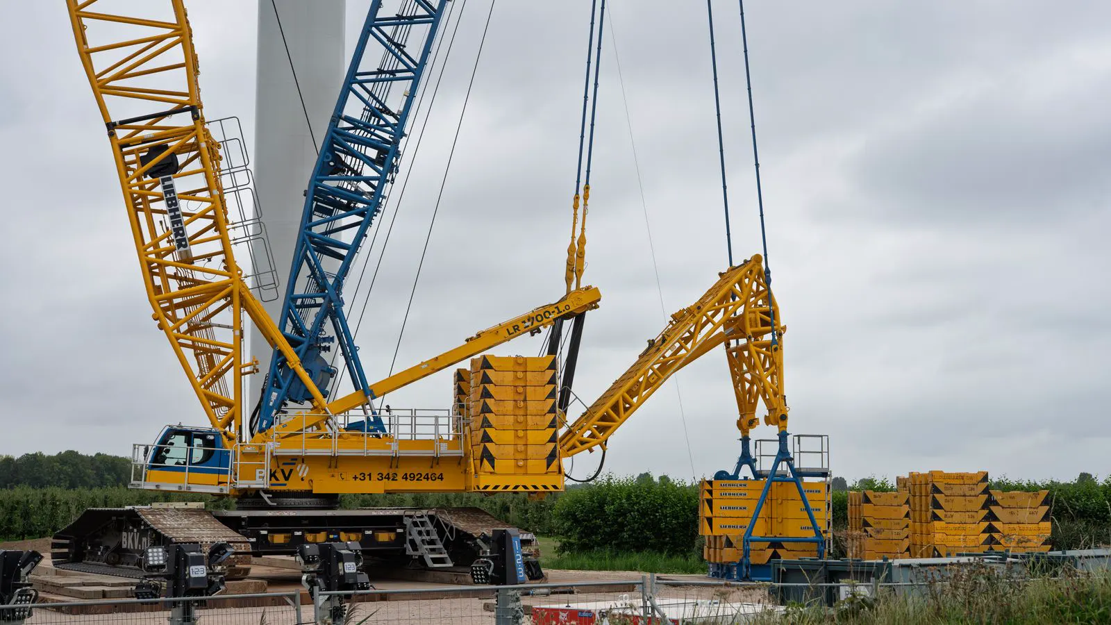
Crane load radius calculation requires measuring horizontal distance from the boom pivot to the load center of gravity. This process determines the specific lifting capacity available for a given radius. Accurate planning prevents overloading and ensures safe material handling on construction sites.
- Measure horizontal distance from the boom pivot, not the base of the machine.
- Check the capacity chart at the exact radius and boom angle.
- Subtract counterweight and rigging weight from the rated capacity.
- Apply derating factors for wind, terrain, and boom configuration.
- Verify calculations with a second engineer before execution.
Prerequisites for Accurate Calculations
Start with the specific load data. You need the net weight of the material, the weight of all rigging gear, and the dimensions of the load. Without these figures, any calculation is a guess. The operator must also know the crane model and current counterweight configuration.
Gather the site conditions before you begin. Wind speed, ground bearing capacity, and nearby obstacles affect the usable radius. If the ground is soft, the crane may settle during the lift. This changes the geometry of the boom and reduces the effective capacity.
Bring the manufacturer’s capacity chart and the operator’s manual to the table. These documents contain the base data for the crane’s maximum rated capacity. They are not just reference sheets. They are the legal basis for the lift.
Step 1: Identify the Load Center of Gravity
Locate the center of gravity of the object you are lifting. For a uniform block, this is the geometric center. For an irregular machine, use the manufacturer’s weight distribution data or a balance test.
The reason for this step is that the load must be suspended directly below the boom tip. If the center of gravity is off-center, the load will swing. This swing increases the effective radius and reduces the margin of safety.
Mark the center of gravity on the lift plan. Note the horizontal and vertical distances from the hook point.
Step 2: Measure the Horizontal Radius
Measure the horizontal distance from the crane’s pivot point to the center of gravity of the suspended load. Use a laser measure or a tape line. Do not measure from the base of the tracks or the outrigger pads.
The reason for measuring from the pivot is that the capacity chart is based on this specific distance. The pivot is the point where the boom rotates. The radius is a straight line from this point to the load.
If the load is swinging, calculate the radius at the maximum swing angle. This is the worst-case scenario.
Step 3: Consult the Capacity Chart
Find the row in the capacity chart that matches your boom length and angle. Then find the column for your calculated radius. The intersection gives the maximum rated capacity.
The reason for using the specific boom angle is that capacity changes as the boom rises or lowers. A boom at 45 degrees has a different capacity than the same boom at 60 degrees.
If your radius is between two chart values, use the lower capacity. Do not interpolate. Always take the conservative value.
Step 4: Subtract Rigging and Auxiliary Weight
Subtract the weight of slings, shackles, spreader beams, and any other gear attached to the load. This total is the rigging weight.
The reason for this subtraction is that the crane must support the load plus the gear holding it. If you ignore this weight, you are lifting more than the chart allows.
Add the weight of any auxiliary equipment, such as a hook block or a crane extension.
Step 5: Apply Site Condition Deratings
Check the wind speed at the site. If the wind exceeds the crane’s rated wind limit, reduce the capacity or stop the lift. The reason for this is that wind creates lateral forces that the crane must resist.
Check the ground conditions. If the crane is on soft soil, apply a derating factor based on the bearing capacity. The reason for this is that sinking reduces the stability margin.
If the crane is lifting over a trench or an uneven surface, apply a further reduction. The reason for this is that the center of gravity of the crane shifts.
Step 6: Calculate the Working Load Limit
Subtract the rigging weight and apply the derating factors to the rated capacity. The result is the Working Load Limit. This is the maximum weight of the material you can lift safely.
The reason for this step is to create a safety margin. The Working Load Limit accounts for real-world conditions that are not present in the idealized capacity chart.
Do not exceed this limit under any circumstances.
Step 7: Verify with the Operator
Share the Working Load Limit with the crane operator. The operator must confirm that the load is within the crane’s safe operating envelope.
The reason for this step is that the operator has the final say on the lift. They can see conditions that the engineer might miss, such as a slight tilt in the boom or a change in wind.
Get the operator’s sign-off on the lift plan.
Common Mistakes in Calculations
Measuring from the base instead of the pivot is the most common error. This leads to an overestimate of capacity.
Ignoring the swing radius is another frequent mistake. A swinging load has a larger radius than a static load.
Using the wrong boom angle is a subtle but dangerous error. The capacity chart is specific to the angle.
Forgetting the counterweight configuration is also common. Different counterweights change the capacity.
Verification Step
Before the lift, perform a final check. Measure the radius again. Confirm the weight of the load. Check the wind speed. Review the capacity chart one last time.
The reason for this final verification is to catch any last-minute changes. A load might be heavier than expected. The wind might have picked up. The boom angle might have shifted.
If any value changes, recalculate the Working Load Limit. Do not proceed with the old number.
Table: Typical Derating Factors
| Condition | Derating Factor | Reason |
|---|---|---|
| Soft ground | 0.8 to 0.9 | Reduced stability margin |
| Wind above rated | 0.7 to 0.8 | Lateral forces increase |
| Lifting over trench | 0.9 | Shifting center of gravity |
| Extended boom | 0.8 | Reduced structural capacity |
| No derating | 1.0 | Ideal conditions |
Final Checks Before Execution
Review the lift plan with the site supervisor. Ensure all personnel are clear of the lift zone. Check the communication plan between the operator and the signal person.
The reason for these checks is that a correct calculation is only half the battle. The execution must match the plan.
If any doubt arises, stop the lift. Recalculate. Do not take risks.
Frequently asked questions
What is the difference between rated capacity and working load limit?
Rated capacity is the maximum weight the crane can lift under ideal conditions. Working load limit is the maximum weight you can lift after accounting for site conditions, rigging weight, and derating factors.
How do I measure the radius if the load is swinging?
Measure the horizontal distance from the pivot to the center of gravity at the maximum swing angle. Use this larger radius for your calculation.
Can I interpolate between capacity chart values?
No. Always use the lower capacity value when the radius falls between two chart columns. Do not estimate a value in between.
Why do I need to subtract rigging weight?
The crane must support the load plus the gear holding it. If you ignore the rigging weight, you are lifting more than the chart allows.
What if the wind speed changes during the lift?
Stop the lift if the wind exceeds the rated limit. Recalculate the working load limit if the wind changes. Do not continue with the old number. ===END===